


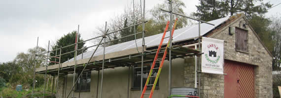
3.5Kwp Suntech Array using SMA SB3000HF-30 inverter, Camerton, Bath
Surge Suppression
Surge Arrestors
To protect any PV system from a direct lightning stroke is practically impossible, due to the amount of energy which can potentially be transferred.
Electronic equipment can be particularly vulnerable to lightning induced surges and good system design, shielding, earthing and bonding may not always provide adequate protection. Surge arrestors can provide expensive or sensitive electronic equipment with a last defence to such damage.
Surge arrestors generally act as voltage limiting devices - switching to a low internal resistance once a threshold voltage is exceeded. Connected between a conductor and earth under normal conditions, no current will flow. However, surges above a clamping voltage are shorted to earth. Clamping voltages will vary for any arrestor depending upon the current being conducted.
Various types of arrestor are available, e.g. silicon oxide varistors (SOV), metal oxide varistors (MOV), silicon avalanche diodes (SAD). MOVs have been commonly used to provide protection, however they degrade over time, consume small amounts of power and can catch fire unless fuse protected (unfused MOVs should not be used inside a building). DC rated SOVs are available with none of these problems and in single, simple to mount packages ready to connect between DC positive, DC negative and earth. Similar units are also available for an AC supply.
A large number of systems have surge suppression built into the PV systems on both the DC array side, and the AC inverter side.
The risk of induced voltages and transients along the incoming service cable is greater, especially in rural areas, where supply is by long overhead lines. As such, surge suppression devices are best fitted at the main incoming point of AC supply (at the consumers cut-out), if the risk of surges and transients merits it. This makes surge protection more effective in being located at the main likely point of entry, and access to the incoming conductors and main earthing terminal more convenient.
Code requirements
The current draft of part 7-712 of IEC60364 does not specifically detail lightning
protection for PV systems. Guidance was provided that - "in the absence of a lightning protection system, the line conductors L+ and L- … should be protected by the use of an overvoltage protective device, located near the inverter. Where surge arrestors are to be used, they should be of the metal oxide or comparable type. The inception and extinction voltage shall be at least 1.4 times the value of Voc stc."
Similarly, lightning protection is excluded from the scope of BS7671 - the IEE wiring regulations, except where the equipotential bonding of lightning protection is laid down. The relevant document is BS 6651, "Protection of Structures against Lightning".
The Dutch Guidelines similarly refer to a Dutch standard for assessing increased risk, but state that the risk associated with the installation of a typical PV system to be "very small". Where a PV system is to be installed within "a few meters" of a lightning protection system, it states that the PV array frame should be bonded to the lightning protection system. In such a case a supplementary equipotential bonding conductor, bundled with the AC and DC cabling, is also required.
The US code has no specific requirements with regard to lightning protection on PV systems, though arrestors are briefly mentioned elsewhere in the code. All exposed metal parts of the PV system are required to be earthed regardless of the location or system voltage.
Summary of Recommended practice
• The main objective in the mitigation of overvoltages is to reduce the loops between the AC wiring, DC wiring and grounding structure.
• Running long DC array cables in earthed metal conduit/trunking will act to both
shield the cables from inductive surges and, by increasing inductance, attenuate surge transmission.
• Supplementary surge arrestors can be fitted to the PV system at key locations.
Arrestors can be fitted at the inverter end of the DC cabling or at both ends for
systems with a long DC cable run. Arrestors can also be fitted to the AC cabling
either at the inverter or at the supply point. Where used to protect equipment,
maximum protection is achieved by fitting the arrestors as close as is practical to the device. These devices however must be electrically safe, and pose no electrical fire hazard.
• Good earthing of array frames will allow any lightning induced currents to flow to
earth.
• Where an existing lightning conductor is present, then consider bonding the array frame to it. If there is any doubt as to whether lightning poses a high risk, then a risk assessment hould be carried out.
Where there is a perceived increase in the risk of direct strike as a consequence of the installation of the PV system, specialists in lightning protection should be consulted with a view to installing a separate lightning protection system in accordance with BS 6651.